Next part of RTL-SDR tutorial – this time we will focus on SDRSharp interface.
After running basing transmission using previous PART #3 it’s time to get to know some basics about SdrSharp interface:
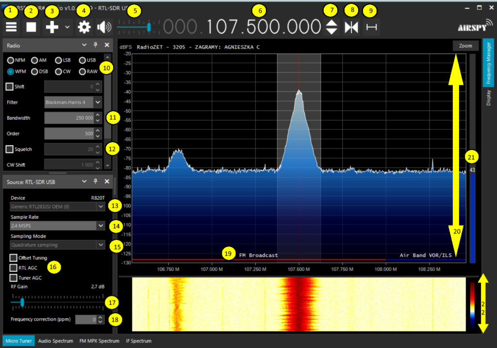
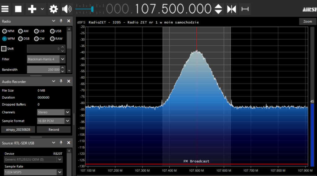
I prepared this graphics explaining basic functionalities (I am still learning graphics)
1 – SDRSharp Menu
Here we have menu with panels available
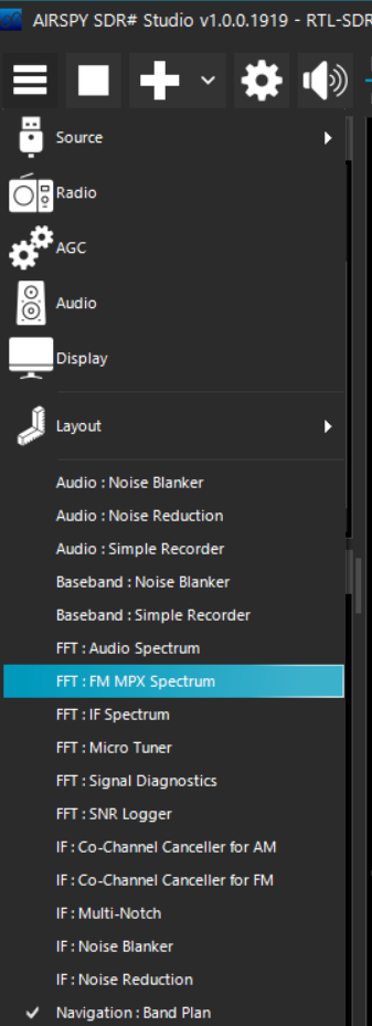
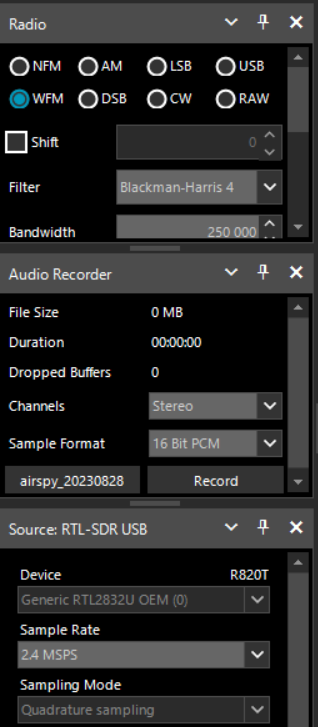
Interface is organized in so called “panels” which we can put anywhere we want
Or dock for example to the left panel
2 – Play or stop button
Showing if your source of signal is running or not. This case – out usb receiver
3 – Add new spectrum slice – new SDRSharp interface
Where we can “clone” part of spectrum currently seen to listen on multiple frequencies
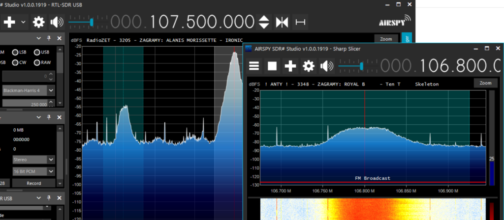
4 – Configure source of SDRSharp
What it basically does is opening source configuration panel if we hadn’t opened it earlier. In our case it is already docked to the left panel
5 – Volume
Simply volume slider
6 – Frequency
Frequency we are tuned into right now. We can change it by clicking on number with left-click or scrolling mouse
7 – Increase/Decrease frequency
It simply does what mouse scrolling – changing frequency up or down
8 – Tuning “style” change
Free tuning – when you change freqency, whole spectrum doesn’t move
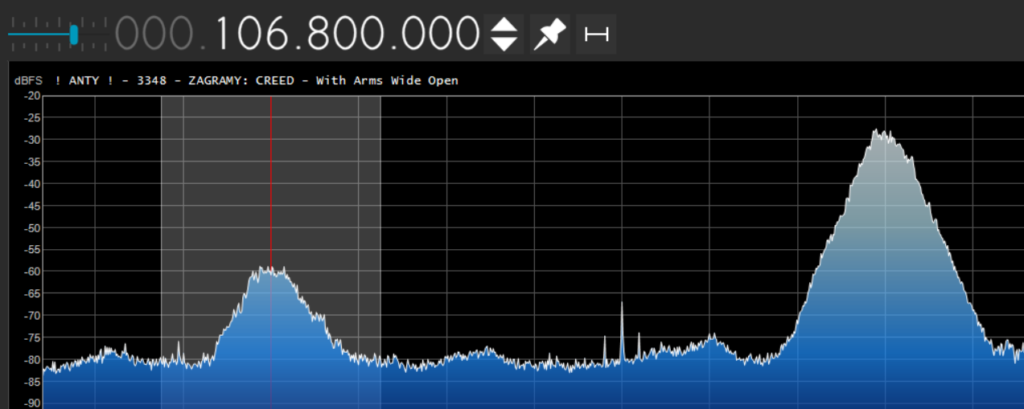
Center tuning – tuned frequency always in the middle of spectrum
Sticky tuning – behaves similar to free tuning
9 – Step
Amount of which frequency moves when you scroll or use freqency up/down buttons. It is determined most of the time by bandplan which will be covered later and linked here. For example for broadcast radio it is 100 kHz
[Will be covered in further articles and linked here]
10 – Modulation
Switch to desired modulation. Basically most voice transmissions below 30 MHz is AM or LSB/SSB, anything up is NFM, and broadcast radio is WFM
11 – Bandwitch
It determines how much of a spectrum you want to currently use. For WFM (Broadcast Radio) it will be mostly between 200-250 kHz, for NFM 12.5 kHz, for AM around 10 kHz and LSB/SSB around 3 kHz
12 – Squelch
Mostly used for NFM transmissions, blocking noises until transmission is heard. Very useful. Set number until you don’t hear noises. Careful! Setting squelch too low may cut weak signals
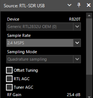
13 – Device
If you have more than one receiver, here is to place to choose. In our case RTL-SDR USB
14 – Sample rate
It’s basically how much of a watterfall you can see at once. For example if setting is 1.024 MSPS (Megasamples per Second) you can see rougghly 1 MHz. For most of modern computers setting up to 2.4 will be OK. Above can cause instabilities
15 – Sampling mode
It can be set only when usb receiver not in use (press stop button). Some dongle supports signal directly from RTL2832 chip bypassing tuner to receive signals below 30 MHz. Unfortunately green one does not so we can leave it as it is
16 – AGC and Offset tunning
Gain is basically changing sensitivity of your receiver. Basically you have to use slider when transmission is not clear enough. RTL and Tuner Auto Gain Control is generally not recommended – those are automatic settings not always suitable for your needs. Offset tuning is setting applied only to older tuners (for example blue one) to eliminate center peak in your spectrum.
17 – Gain slider
As explained earlier – only slider for gain. Most common settings is somewhere in the middle
18 – Frequency correction (ppm)
Property mostly used in cheaper (blue or other) receivers without TCXO (crystal oscilattor) which is making sure you see frequency where it is. Without it you may have to correct your receiver for example by finding local broadcast station, tuning to it and then clicking ppm property to be on frequency where it should be. NOT applied to green receiver
19 – Bandplan
Every country has so called bandplan. It shows what can be transmitted in selected frequency. In SDRSharp we see some default settings which may not be accurate for every country
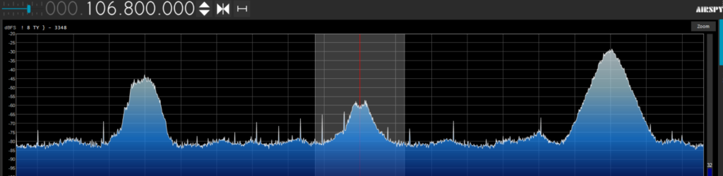
20 – RF spectrum
Showing signals and its strength around tuned frequency
21 – Signal strength
Basically showing signal strength on tuned frequency
22 – RF watterfall
Showing signal strength history using scale from red (strong) to blue (weak)
Congratulations you have managed to see every basic setting for using SDRSharp interface. If some terms are not clear yet don’t you worry – it will be covered in next posts
For additional info – read full guide HERE